
TECHNOLOGY FOCUS
Filters are one of the fundamental building blocks of RF and microwave systems, along with amplifiers, oscillators, mixers, and switches.
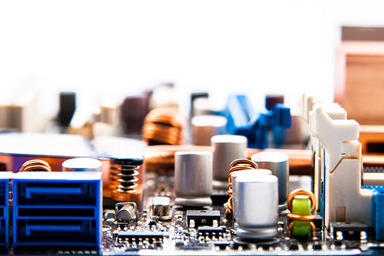
When we design a printed circuit board (PCB) based system, we rely on surface mount technology (SMT) components to realize a very compact, low cost system. Although there are now some standard filter designs available in SMT format, we often need to design a custom filter or multiplexer. These custom filter designs can be realized using standard SMT inductors and capacitors and perhaps a few printed distributed structures as well.
Successful designs have been demonstrated across a frequency range of tens of MHz up to 6GHz. This frequency range covers most of the current wireless standards and many of the military communications bands as well.
COURSE CONTENT
This course is devoted to the fundamentals of practical filter design for RF and microwave systems in a low cost, PCB environment.
The central challenge is to identify the most useful filter topologies for this construction method and frequency range. The search for a useful topology must include knowledge of each component's spurious response. Various SMT component libraries will be examined with this in mind.
Another serious challenge to the designer is the rather limited catalogue of standard component values that are readily available. Simple techniques to overcome this limitation will be demonstrated. Although the majority of designs are fixed in frequency and bandwidth, some tunable bandpass and notch filter topologies will be presented.
We will apply EM simulation to our designs when the layout becomes highly compacted, or when non-standard connections to library components are required. EM simulation will also be used to optimize the performance of edge launched PCB connectors.
Example filter designs that cover a broad range of applications will be presented with measured data and error analysis.
The instructor will choose examples to develop based on the interests of the class.
The course material is suitable for filter designers, designers of other components, systems engineers, and technical managers.
WHO SHOULD ATTEND
The course material is suitable for filter designers, designers of other components, systems engineers, and technical managers.
Introduction to PCB Filter Design
We will start with a brief discussion of PCB construction techniques and how they affect our filter designs.
Then we will turn to basic filter design concepts. Starting with lowpass prototypes, we will touch on Chebyshev and elliptic prototypes and finding prototype element values.
Next we will turn to the concept of cross-couplings and how they introduce finite transmission zeros.
Finally, we will discuss some of the more useful filter topologies we have found for PCB based bandpass and notch filters.
- Basic PCB Construction
- Basic Filter Concepts
- Chebyshev and Elliptic Prototypes
- Cross-Coupled Filters
- Useful Bandpass Topologies
- Useful Bandstop Topologies
PCB Filters and Connectors
The bulk of this session will be devoted to examples of Chebyshev and elliptic function filters that have been built using standard SMT components. In most cases we will show the evolution of the design from ideal lumped prototype to final layout with comments on the design decisions that were made.
Before we can measure our filters we need a reliable transition from the PCB to our connector of choice. SMA edge launch connectors are quite popular and are available in several styles.
We will spend a few moments discussing how to optimize these connectors for higher frequency performance.
- Lowpass Filter Examples
- Bandpass Filter Examples
- Notch Filter Examples
- Diplexer Examples
- Multiplexers
- Edge Launch Connectors